Scanning and CAD Modeling for Industrial Equipment

Equipment, Capabilities
Scanning Platforms
- CMM Laser Scanners
- Portable CMMs with Laser Scanning
- CT Scanning (internal geometries)
Software Platforms
- Geomagic
- Polyworks
- SolidWorks
- AutoDesk Inventor
Support Capabilities
- Robust Inventory Control System
- 2,000 lb hoist capacity
- Polishing Wheel
- Cutoff Machine
- Horizontal Bandsaw
- Parts Cleaning Station
Qualifications, Accreditations, and Certifications
ITAR Registered
ASQ Certifications
All inspectors are certified to one or more of the following:
- CQI (Certified Quality Inspector)
- CMI (Certified Mechanical Inspector)
- CQT (Certified Quality Technician)
- CQE (Certified Quality Engineer)
- CQM (Certified Quality Manager)
- CQA (Certified Quality Auditor)
Plastics Technology
All CAD Specialists have completed Designing Plastic Parts for Injection Molding studies.
- Duns Number:19-993-4829
- NAICS: 541380 (Mech. Testing Lab or Services)
- Cage Code: 0GB04
- SIC Code: 8734
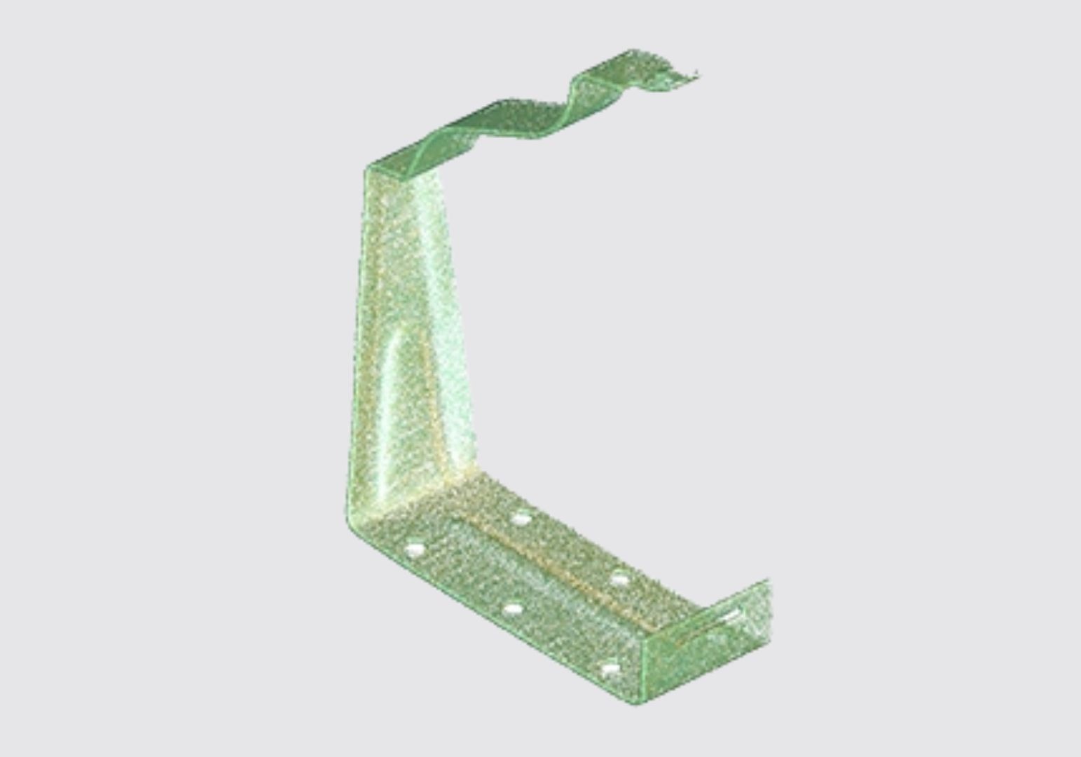
Scanning Outputs
Point Cloud
- Raw 3D Scan Data (.txt, .asc)
Generated by all 3D scanning technologies, raw geometric data is collected as a point cloud. This is the first step in every project.
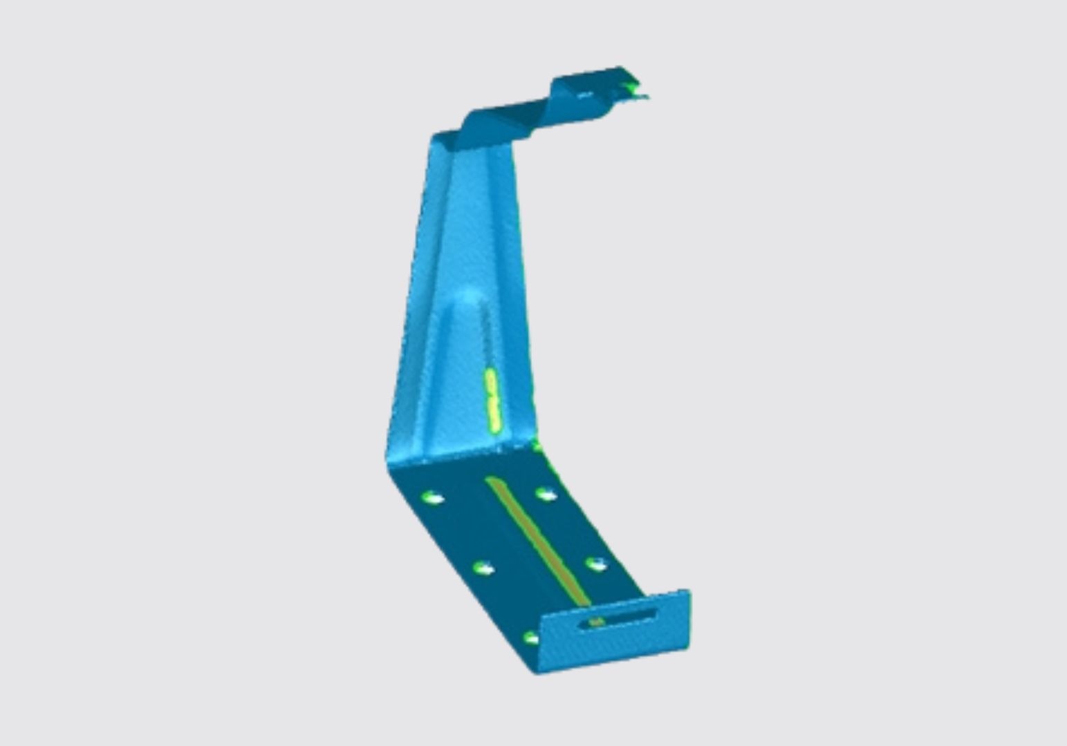
Polygons
- Raw 3D Scan Data with a polygonal wrap (.stl)
Neutral file primarily used by the 3D printing industry.
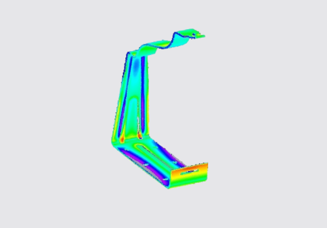
Analysis
- 2D Visual Report (.pdf)
- 3D Interactive Report (.pwzip)
Point cloud data is overlaid to an existing CAD model or scan data of another part to show deviation. Used for rapid design verification, tooling validation, and first article inspection.
Referred to as a Deviation Analysis, Comparative Analysis, Computer Aided Inspection (CAI) or Verification (CAV), or Color Map. Reports can also be manipulated to show specific dimensional call outs or FAIs. We call this a "CAV Plus".
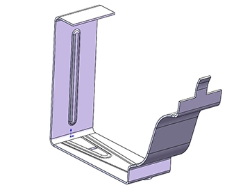
Modeling Outputs
Native Parametric Formats
Models developed in your native CAD platform. Constructed with a fully functional design tree, robust models are built for ease of editing.
NURBS File Format
Best for modeling organic shapes that do not need to be edited. Surface or solid file output (.igs, .stp)
All Reverse Engineering and Modeling project customers receive a Live Model Review at project completion.
Scanning vs CMM Inspection
When you may need dimensional inspection vs 3D scanning.
Does your inspection involve a large number of dimensions?
Measuring multiple features can be done with both a traditional CMM and by extracting the data from a 3D scan. However, it is generally more efficient to extract a few dimensions from a 3D scan than several hundred. As a guide, 20 (or fewer) dimensions on 1 or 2 parts is a good number for 3D scanning. As the dimensions and number of pieces increase, programming and inspecting with a CMM is more cost effective.
Helping you find the best solution.
IIA is dedicated to helping you solve your quality and design challenges. In these situations, we work with IIA Inspection to create solutions that are comprehensive, cost-effective, and appropriate to achieve your goals.
Testimonial
"In a hyper-focused myopic state I had the models to be scanned shipped out to your people before confirming the schedule. Your team could have justifiable said 'your timing problem is not our problem!'
Instead, in seamless fashion, first contact with Steve led me to a quote from Julie and Ryan is getting us what we need. We got client approval Tuesday afternoon, shipped the models to you, and our first scans were in hand by Thursday afternoon.
Excellent team work."
- Jonathan T, bleck design group
Story-Worthy Lab and Engineering Services
Built for responsiveness.
IIA strives to provide services worth telling others about. We've structured our entire operation to be responsive to your needs – from precision equipment to one-off widgets.; we strive in every way to provide story-worthy service.
To take you to the next step.
When you begin a project with us, we'll want to know your stated and unstated project needs. We value making and keeping aggressive commitments to help you get to the next step in your project. You’ll know the accuracy of the CAD model we provide by attending a live on-line review of the CAD geometry compared to the scanned part.
Moving your project forward
When you partner with IIA, we start by listening to your project needs and goals. We then make and keep aggressive commitments to move your project forward to the next phase. Our services include a live online review of the CAD geometry compared to the scanned part, so you’ll have an in-depth understanding of the accuracy of the CAD model we provide.