Scanning and CAD Modeling PlasticsPlastics Manufacturing
Your molding development, qualification, and product launch process often requires several verification steps before full production. You may need to reach beyond your internal experts for help.
Rapid Part Verification
Industry expertise is top of mind when considering working with someone outside of your organization. At Industrial Inspection & Analysis (IIA), our injection molding experts must complete studies in the Design of Plastic Parts for Injection Molding, so they can fully understand your needs.Our expertise includes 3D scans and comparative analyses —invaluable tools for rapid decision-making. Our CAD models are developed with draft, parting lines, and a full design feature tree per your requirements.
When you make IIA an extension of your team, you can expect a personalized project managed by a highly skilled professional with whom you have direct communication.
Why Choose IIA?
Our team brings decades of experience in the inspection of molded parts to every job — and the knowledge base that goes along with that. Our expertise ranges from the ability to identify burns, short shots, flash and warp to the expert analysis of mold flow.With locations across the U.S., our labs have amassed an impressive array of state-of-the-art measuring tools and technologies, including the latest touch and vision CMMs, to deliver data you can depend on.
Together, our team and technologies allow us to provide high-quality, cost-effective service that is unmatched in the industry. Our injection molding experts are just a call or click away!
NEED A QUOTE?
Simply fill out your name, number, and email below and someone from our team will contact you within 24 hours.
Equipment, Capabilities
Scanning Platforms
- CMM Laser Scanners
- Portable CMMs with Laser Scanning
- CT Scanning (internal geometries)
- Polymer Analysis
- Melt Flow Index
Software Platforms
- Geomagic
- Polyworks
- SolidWorks
- AutoDesk Inventor
Support Capabilities
- Robust Inventory Control System
- 2,000 lb hoist capacity
- Class 10,000 Clean Room Inspection
- Parts Cleaning Station
Manufacturing Inspection Services
Fluid Testing & Analysis
Our ISO-accredited labs provide a full menu of fluid testing and analysis to monitor the health of equipment and machinery used in plastics manufacturing. Our ASTM-compliant services include testing and analysis of lubricating oil, fuel, coolant, grease, transformer oils, and other equipment fluids.
Cybersecurity Testing
IIA offers cybersecurity testing and certification to help manufacturers enhance the security of wireless products and comply with changing regulations. Our cybersecurity testing meets requirements in the United States (FCC), European Union (CE) and United Kingdom (PSTI).
Specific Absorption Rate (SAR) Testing
SAR testing helps to ensure that devices operate within mandated limits before they are marketed to consumers. We use precision equipment to test for compliance with local and whole-body specific absorption rate limits from 4MHz to 10GHz.
Global Market Access (GMA)
Our GMA experts can help you gain the approvals needed to sell your product internationally. From start to finish, we can help you navigate complex regulations and get your product to market in more than 180 countries.
Dimensional Inspections (Metrology)
Vast industry experience and 24-hour operations make IIA the most efficient, effective and trusted leader in dimensional inspections. IIA uses your specifications to conduct First Article Inspections and capability studies, and all of your projects are personally managed by a highly skilled technician or engineer who will communicate directly with you.
Lab Services
Our state-of-the-art laboratories use metrology, scan-to-CAD comparisons, and a variety of complementary NDT methods to paint a comprehensive picture of your component. When a part is too large or too delicate to ship, our labs can provide on-site NDT testing and quick turnaround times. We are also equipped to perform a variety of destructive testing on automotive parts, including mechanical properties, chemical composition, microstructural/heat treat analysis, and more.
Lift Services
Our Lift Services team is a leader in performing non-destructive testing to ensure that lift equipment is structurally sound and safe to use. We offer a wide variety of complementary NDT, including magnetic particle testing (MT), ultrasonic testing (UT), visual and operational inspections — and more. Our team includes engineers with expertise in the fabrication, installation and repair of crane systems.
Inspection Services
Our Inspection Services experts are highly experienced in Advanced Non-destructive Examination (NDE), traditional NDE, and IIA patented specialty NDE methods. We can also perform RVI in tanks, pipes, tubes and vessels in your manufacturing plant.
Qualifications, Accreditations, and Certifications
ITAR Registered
ASQ Certifications
All inspectors are certified to one or more of the following:
- CQI (Certified Quality Inspector)
- CMI (Certified Mechanical Inspector)
- CQT (Certified Quality Technician)
- CQE (Certified Quality Engineer)
- CQM (Certified Quality Manager)
- CQA (Certified Quality Auditor)
- Duns Number:19-993-4829
- NAICS: 541380 (Mech. Testing Lab or Services)
- Cage Code: 0GB04
- SIC Code: 8734
Scanning Outputs
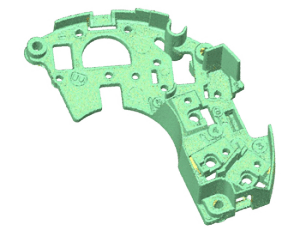
Point Cloud
Raw 3D Scan Data (.txt, .asc)
Generated by all 3D scanning technologies, raw geometric data is collected as a point cloud. This is the first step in every project.
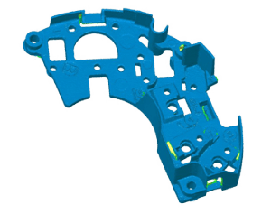
Polygons
Raw 3D Scan Data with a polygonal wrap (.stl)
Neutral file primarily used by the 3D printing industry.
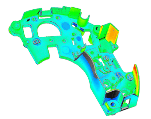
Analysis
2D Visual Report (.pdf)
3D Interactive Report (.pwzip)
Point cloud data is overlaid to an existing CAD model or scan data of another part to show deviation. Used for rapid design verification, tooling validation, and first article inspection.
Referred to as a Deviation Analysis, Comparative Analysis, Computer Aided Inspection (CAI) or Verification (CAV), or Color Map. Reports can also be manipulated to show specific dimensional call outs or FAIs. We call this a "CAV Plus".
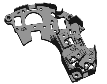
Modeling Outputs
Native Parametric Formats
Models developed in your native CAD platform. Constructed with a fully functional design tree, robust models are built for ease of editing.
NURBS File Format
Best for modeling organic shapes that do not need to be edited. Surface or solid file output (.igs, .stp)
All Reverse Engineering and Modeling project customers receive a Live Model Review at project completion.
Testimonial
"Not sure how to say this besides - THANK YOU for the quick turn-around! Our customer wanted a big job completed quicker than we could handle. Your group jumped right in and got it going.
We look really good to our customer and their project is rolling along nicely!"
- John W, TechNH, Inc.
Story-Worthy Engineering Services
Built for responsiveness.
IIA strives to provide services worth telling others about. We've structured our entire operation to be responsive to your needs – from precision equipment to one-off widgets; we strive in every way to provide story-worthy service.
To take you to the next step.
When you begin a project with us, we'll want to know your stated and unstated project needs. We value making and keeping aggressive commitments to help you get to the next step in your project. With equipment and skills specifically developed for precision components, we’ll find the best approach to completing your project. You’ll know the accuracy of the CAD model we provide by attending a live on-line review of the CAD geometry compared to the scanned part.