Making the invisible visibleCT Scanning
Want to investigate a fully assembled component to determine whether a seal is effective, or if threads have full interaction?
These are just a few of the ways the emergence of computed tomography (CT) scanning has been a game-changer in the field of non-destructive testing.
Representing the future of Industrial Metrology, CT scanning allows us to capture dense and comprehensive data for dimensional analysis of internal and external features — examinations that were previously impossible with non-destructive methods. With today’s CT scanning technology, it is possible to differentiate between multiple materials or multiple components in an assembly.
While CT scanning produces highly accurate results without physical damage to the part, it is not an ideal testing method for every type of part. Parts that are very large, made of high-density materials, or have very flat dimensions provide a challenge when scanned using this method.
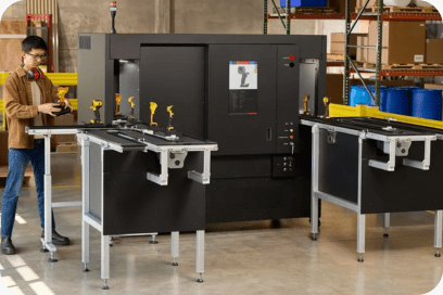
Meet the Lumafield Neptune
Talk To An Expert
Don’t see exactly what you are looking for? Or maybe you do and want more specifics or an estimate. Either way, you can call us at
470-264-5765
right now or just fill out the form below and we will respond back within 24 hours.
Common Uses for CT Scanning
- Threaded assembly interaction
- Leak testing – verification of mechanical seal
- Non-destructive inspection
- Dimensional analysis of internal geometry
- Over molded components
- Failure analysis
- Porosity analysis
- Part-to-part comparison
- Part-to-CAD comparison
- Composite analysis
- Solder ball grid array inspection
- Wall thickness analysis
- Void/inclusion analysis
- Volume/surface area calculations
- Reverse engineering
Materials suitable for CT scanning
Plastics, silicones, rubbers, aluminum, steel, stainless steel, nickel, nitinol, titanium, brass, copper, and many more.
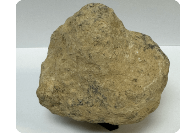
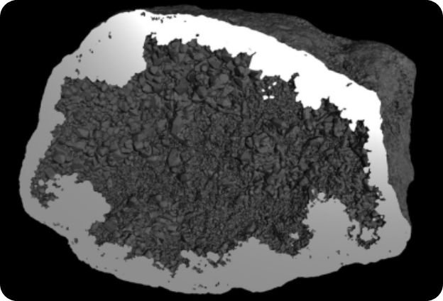
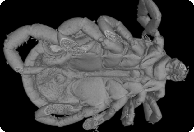
However, CT scanning is not limited to dense metals and other industrial materials. It works equally well with organic, thin, and flexible materials that are otherwise difficult to inspect with traditional methods.
Deliverables
- 2D image stack or video of slices through your part
- 3D volume viewable with supplied Volume Graphics myVGL Viewer Software
- Located .stl file.
- 3D computer aided verification (CAV) with nominal-actual CAD comparison and part to part comparison
- Dimensional inspection report
- 3D PolyWorks dimensional inspection report
- CAD model creation, step, iges, SolidWorks, and Inventor files.
How it Works
CT scanning does not require any external forces such as pressure or stress to be applied on the part being scanned. Instead, it uses an X-ray source to transmit a beam of X-rays through the part. To obtain comprehensive data, your part is rotated through a constant X-ray cone beam. By moving the object closer to the X-ray source, its features can be magnified. Multiple still images are captured at each incremental degree of rotation and the measured flux is averaged. These images show the intensity of X-rays attenuated by the part. Denser/thicker areas appear darker, whereas less dense/thinner areas appear lighter. The resulting images are reconstructed together to create a digital 3D volume that can be viewed for visual inspection or processed further for different analyses, such as dimensional inspection, porosity analysis, or reverse engineering.
Why Choose IIA?
CT Scanning vs. Radiography (X-Ray): Which service is right for you?
CT Scanning is ideal for:
- Viewing internal geometry, cracks, pits, or voids
- Scanning multiple layers
- Dimensional analysis of internal geometry
- Comparative analysis – CAD to part, part to part
- Solder integrity
Choose Radiography (X-Ray) for:
- Large volume of parts
- Full production run or individual parts
- Fast analysis of common defects
- Weld analysis
- Dense metals
Qualifications, Accreditations, and Certifications
- CQI (Certified Quality Inspector)
- CMI (Certified Mechanical Inspector)
- CQT (Certified Quality Technician)
- CQE (Certified Quality Engineer)
- CQM (Certified Quality Manager)
- CQA (Certified Quality Auditor)
- A2LA Accredited to ISO/IEC 17025: 2005
- ASQ Certifications
- ITAR, JCP and SAM Registered
- DCS Certified
- NADCA Participation
- Federal Firearms License
Resources