How to Apply Datums to a Blueprint
(Where to apply datums)
One of the most critical aspects of a blueprint, datums will either aid in producing a functional part that fits to its assembly perfectly, or a useless hunk of metal. The datums on a drawing define the most important functional features on a part and are used for locating on the assembly, as well as for locating of supplementary components that will be installed on the part.
As a general rule, datums should be used to identify the most important or critical features on a part blueprint for later use in determining if the part performs as intended. If used correctly, a datum reference frame will also control the six degrees of freedom.
Determining where to apply datums may seem like a daunting task, but it is simple if you ask yourself these questions when defining your datum definition.
- What are the key features of the product?
- How does my product assemble to other components?
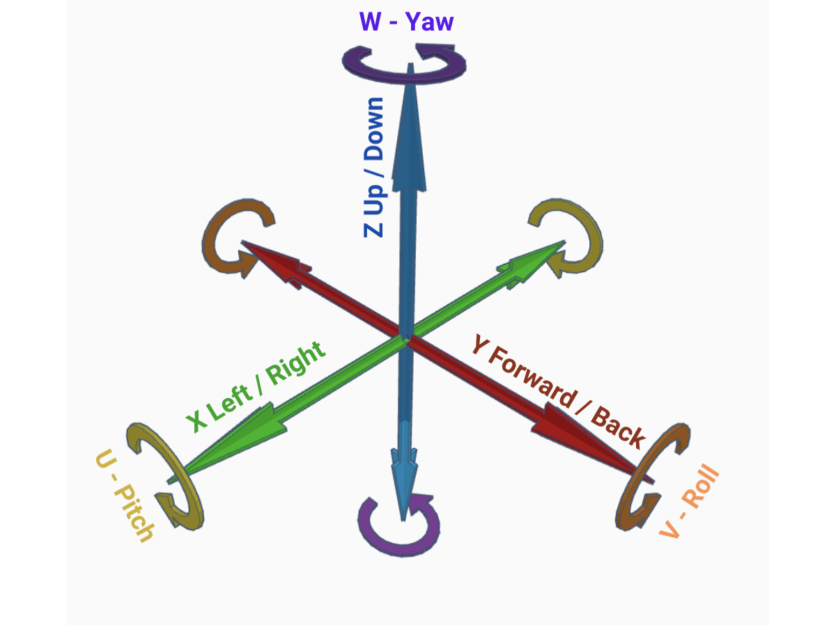
- How can I best control the 6 degrees of freedom?
We will revisit these questions later, but first let’s go over a few of the core questions relating to datums to give a better understanding of their purpose and function.
Having the right team of engineers working behind the scenes will help ensure that your production or exhibit goes off without a hitch. While we can’t guarantee rave reviews, we can ensure something far more important: safety.
What is the purpose of a datum on a blueprint?
The purpose of a datum on a blueprint is to define the key features to be used during inspection as a theoretical exact location to ensure that the product conforms to the fit and function desired by the designer. A datum reference frame is three datum planes that are perpendicular and intersecting.
Typically, in metrology, the primary, secondary, and tertiary datums are used to align to the part as the origin for the X, Y, and Z axis and control the roll, pitch, and yaw. In metrology, the datum reference frames are typically used as the origin for inspection on a Coordinate Measuring Machine.
Once established, the datum reference frame is then used as the basis for determining if a part conforms or does not conform to the respective GD&T feature control frames.
How to identify datums on a blueprint?
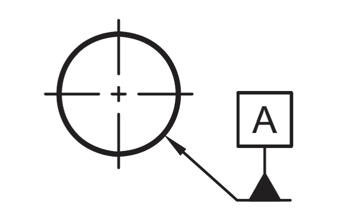
A datum is identified on a blueprint with a letter in a frame, a line leading from the frame to a solid triangle, and a leader line, dimension, or feature control frame that is pointing to or referring to the datum feature.
Per ASME Y14.5 2018, a datum can be applied to a plane, width, cylinder, sphere, cone, linear extruded shape, and complex shapes. A single complex datum can control all six degrees of freedom.
How many datums can a part have?
A part blueprint can have as few as one datum and, theoretically, as many as thousands of datums defined. There are many instances where you would have multiple datum reference frames with unique datums for the primary, secondary, and tertiary, and also datum reference frames that reuse some or all datums.
Where should you put a datum on a blueprint?
A datum should be applied to key features that are to be used during inspection as the theoretical exact location of a feature on the product. The following 3 questions can help you identify features to use as your datums.
- “What are the key features on the product?”
- “How does my product assemble to other components?”
- “How can I control the 6 degrees of freedom?”
What are the key features on the product?
Typically, the primary datum is the feature that has the largest mating surface area, such as a large flat plane that will mate with the assembly and will control 3 degrees of freedom. The secondary datum controls the rotation of the part and is often a plane that is perpendicular to the primary datum or a cylinder or set of two cylinders that are perpendicular to the primary datum. The tertiary datum will control the remaining degree(s) of freedom.
In the example below, primary datum as the top plane is controlling the z location, the roll, and the pitch, the secondary datum is the front plane which controls the yaw and the y location, and the tertiary datum controls the x location.

In the example below, the primary datum (-A-) controls the z location, the pitch, and the roll; the secondary datum and tertiary datum (-B- & -C-) control the rotate; and the secondary datum (-B-) controls the X location and the Y location.

How does my product assemble to other components?
Another question that is important to ask is “How does my product assemble to the other components?”. If your product is installed with pins using two holes it is probably a good general rule to use those locating holes as your datums. Likewise, if the product mates against the outside walls, the mating walls should be used as the datum.
How can I control the 6 degrees of freedom?
Last, but certainly not least, is controlling the 6 degrees of freedom on your product through the datum definition. To ensure that you can reliably locate and measure a part, the 6 degrees of freedom must be controlled. If the origin or rotation on a plane is not controlled, it will invite the possibility of misinterpretation of the dimension or a part that is falsely failing, or even worse, falsely passing.
The only time that the 6 degrees of freedom will not be completely established for the datum reference frame is on a round part that does not have any defining features on the rotation of the diameter. In this case, you will only control 5 degrees of freedom.
Keep in mind, in some cases it is not necessary to control all of the 6 degrees of freedom for each feature control frame to adequately dimension a feature.
For example, the profile opposite of datum A does not need a secondary or tertiary datum because the only basic dimension that is needed to calculate the profile is the thickness from datum A to the profile plane.

Conclusion
Defining datums properly and controlling the 6 degrees of freedom are the most important aspects of a datum reference frame and properly applying GD&T to a feature control frame. The datum definition does not need to be complex. In fact, in most cases, the features that should be used as datums are very clear and obvious.


