Understanding Load Sharing In Multi-Crane Lifts
Multiple crane lifts can be tricky business. One source described two crane lifts as being more than twice as risky as single crane lifts with even more disproportionate increases in risk as more cranes are added. This is generally due to the load interaction between the cranes.
Despite the risks, it is not uncommon for multi-crane lifts to be conducted without the operator’s knowing the exact load that will be lifted by his/her crane. To obtain this most basic piece of information for a multi-crane lift, three factors must be known first. These are the load weight, the load center of gravity (CG), and in some cases, the load geometry.
Of these three factors, the hardest to get is usually the CG. However, the load distribution cannot be calculated accurately without it and this must be impressed upon the owner of the load if the lift is to be done safely. Remember, if we guess at the CG location, we are guessing at the load weight which can lead to accidents.
Calculating Load Shareload share diagram
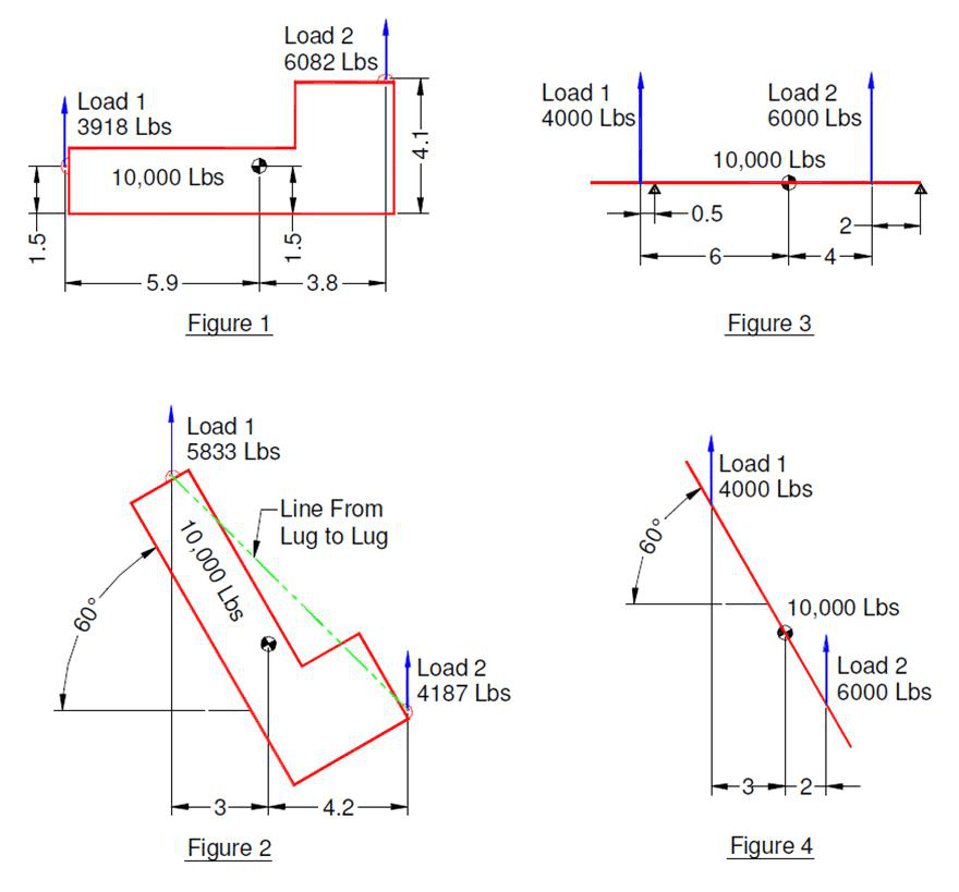
Once we have the necessary data, the load share for each crane can be determined. Note that distances are measured to the lift lug holes from the CG.
For example, for Figure 1 we calculate:
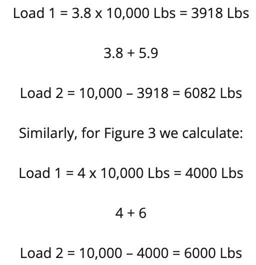
These calculations assume that the crane’s load line is plumb with no side loading. In this case, the relative height of the lugs and CG is not a factor in the calculations.
Guessing The Center Of Gravity
Let’s assume for a moment that the CG is not given. As mentioned above, we are left to guessing its location. Assume again that we miss our guess by 5% of the distance between the lugs. This might seem like a lot, but taking all measurements in feet for Figure 3, the discrepancy is only 6 inches. If the actual CG is 6” closer to the right side than is shown in figure 3, then load 2 will increase to 6,500 lbs from the 6,000 lbs we calculated based on our assumed CG. This is a difference of 8.3% which can be significant when working near the limits of the load chart. Obviously, the worse our guess, the more inaccurate our assumed load distribution. Also, where the distance between the lugs gets smaller, the accuracy of our guess makes a lot more difference to our assumed load distribution.
Tipping Up The Load
Once we begin tipping up the load, we may find that the load distribution between the cranes changes. How much the distribution changes will depend on the geometry of the load.
In Figures 1 and 2, the lugs are at different heights and if we drew a line between the lug holes, the CG does not lie on that line. When this situation occurs, the load distribution will change as the load tips up.
Using the same calculation method as given before, for Figure 2 we calculate that Load 1 will increase to 5,833 Lbs and Load 2 will drop to 4,167 Lbs. Thus, we can see that the load on crane 1 increases by 1915 lbs or 48.9% going from level to a 60 degree inclination. The increase in load must be accounted for in the lift plan. On the other hand, in this case, we can take advantage of the reduced load on crane 2 by booming out to a higher radius if needed. Note that, except for extreme geometries, the shift in load is minor over small changes from level but increases dramatically as the load approaches vertical.
In Figures 3 and 4, we have the idealized case where the lugs are at the same height and if we drew a line between the lug holes, the CG does lie on that line. In other words, the lug holes and the CG are collinear. When this situation occurs, the load distribution will not change as the load tips up provided that the load lines remain plumb. Calculating the loads for Figure 4, we find that Load 1 is 4,000 Lbs and Load 2 is 6,000 Lbs which is the same as for the case of a level load shown in Figure 3. This situation does not permit the tailing crane to boom out further as the load tips up.
Know The Weight Distribution Throughout Lift Sequence
It is important to know the load distribution throughout the lift operation. Often, the resting points for the load are not in line with the lug positions either at the start of the lift, at the end, or both. This must be considered when planning the lift sequence or the bulk of the load could shift to the lighter crane during lift off or set down of the load.
For example, in Figure 3 the triangles show support locations for the beam before it is lifted. If crane 1 were to lift its end off the support before crane 2 began lifting, it would initially carry half the load, or 5,000 lbs. This is because the CG is exactly midway between the lug for crane 1 and the support point on the right side. This is 25% more than we initially calculated for the load being lifted by both cranes.
Conversely, if crane 2 were to lift its end first, it would carry only 5,790 lbs before crane 1 began to lift its end. This is slightly less than our initial calculation of 6,000 lbs with both cranes lifting the load. Thus, the lift sequence for this situation should begin with crane 2 lifting off its supports, followed by crane 1. Similarly, when the load is put down, crane 1 should be put down first followed by crane 2.
In Summary
Obviously, many more precautions are necessary when carrying out a multi-crane lift. Thorough lift planning with engineering involvement for critical lifts and experienced lifting personnel are key success factors. However, understanding the load distribution is the first step to a safe lift.
The examples in this article do not pertain to all situations and lifts involving difficult geometry, flexible components, or more than two cranes are generally more complicated. Always ensure that competent personnel make all load calculations or, where uncertainty exists, contact us and one of our engineers would be happy to assist you.


