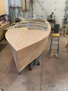
IIA is a pioneer in the use of 3D scanning for reverse engineeringReverse Engineering
IIA is a pioneer in the use of 3D scanning for reverse engineering, geometry recreation and 3D modeling.
Common Applications for Reverse Engineering
Let Our Experts Help
Whether you need timely inspections, would like an estimate, or have an emergency and need help right away, we are here for you.
Call us at
470-552-8301
or complete the form below, and we will be in touch within 24 hours.
Digitizing and Scanning
IIA has vast and varied digitizing and scanning capabilities with accuracies smaller than .0001 inches and XYZ coordinate data collection at rates beyond thousands of points per second. The scanned data can be recorded and/or converted in terms of points, conventional curves, splines, surfaces and solid models. This data is often used to define or analyze complex geometry, such as vane and blade profiles, and can also play a key role in comprehensive and sophisticated reverse engineering processes.
Parametric Models
Parametric models are developed in your native CAD platform (SolidWorks, Inventor, etc). Constructed with a fully functional design tree, our models are built for ease of editing and intuitive use.
Modeling Platforms (Software)
We can build files for use in any modern software, and many legacy platforms. Our primary CAD platforms are SolidWorks and Inventor, each fully up to date with the latest versions. We retain legacy licenses for those customers who need it. If we do not have your cad software of choice, we can output neutral file formats such as .igs, .stp, .x_t, and many more.

NURBS models
Typical output of a geometry re-creation/reverse engineering project, NURBS models are best for recreating exact organic shapes that do not need to be edited. These can be combined with parametric shapes as "hybrid" models.
Download sample models.
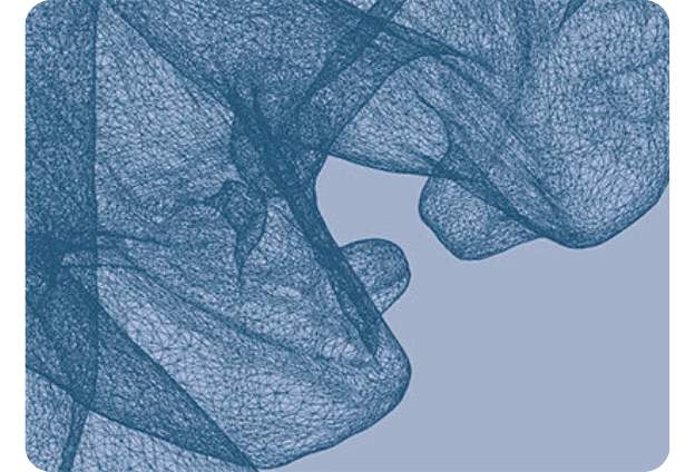
Raw File Formats
Any scanning project will produce a point cloud. Point volume can range from 20,000 data points on smaller objects to several million on larger parts. These are very heavy files, and they require special software to manipulate. Raw point data can be supplied as a stand-alone deliverable or (more often) alongside any of our other deliverables.
Download sample raw files.
Golden Models
If you need to determine tolerances from your product manufacturing process, a common approach is to measure many known good parts basing the tolerances on detected variations. IIA has the ability to scan multiple parts and average them all into one nominal CAD model, commonly referred to as the “golden model”.
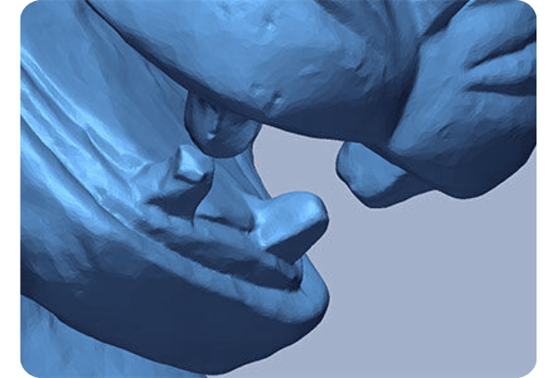
Making Polygonal Wraps
STL files are used industry wide for 3D printed prototypes, designing packaging around a part or assembly, and for taking precise surface area measurements. They are created directly from the raw scan data by creating a polygonal mesh from the scan points.
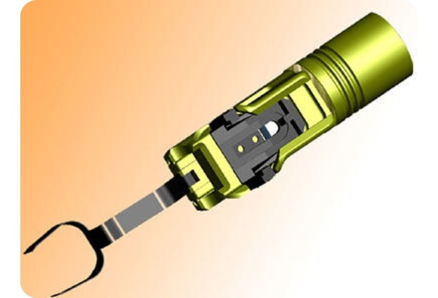
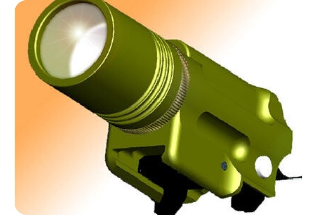
3D CAD Solid Modeling
CAD Solid Modeling is the process of building a virtual three-dimensional representation of a given part, product or object. It is used for a variety of purposes, such as geometry visualization, creating parametric-based drawings, programming CNC machine operations (CAM), 3D analyses, and finite element analysis (FEA).
IIA can make a parametric 3D solid model from your prototype or drawing or design one based on your specified parameters. Solid models, especially those with complex surfaces, are tested and verified to confirm accuracy requirements are met.
IIA recognizes that many reverse engineering jobs are not complex and don’t require scanning at all. We can help you turn your napkin sketch or hand drawn ideas into a workable 3D CAD model, as well as, professional part or assembly drawings.
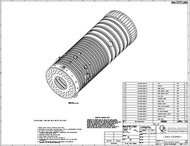
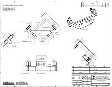
Engineering Drawings
IIA provides engineering drawings that meet stringent requirements, including ANSI Y14.5. The drawings can be generated from parametric 3D solid models, also created by IIA, or from a model you provide. We can also convert old paper drawings to CAD format for advanced quality control and easier maintenance.
Tips to Help Us Provide an Accurate Quote
Before you start your next modeling or reverse engineering project, here are some things to consider:
Verification & Project Handoff
Every project ends with a conference call or screen share to ensure that the results are understood and meet your requirements. IIA uses its own Deviation Analysis process as a final proof-of-work at the end of every reverse engineering project to demonstrate a precise point-by-point comparison that each feature and each characteristic is accurate to the scanned part. This level of precision in verification is virtually impossible with manual methods. A Deviation Analysis makes full verification cost-effective and is critical to assure the accuracy of the resulting model.
Certifications and Guidelines
- ISO/IEC 17025: 2005
- ISO/IEC 17065: 2012
- ITAR Registered
- FAR Part 145 Certification
- Federal Firearms License (FLL)
- NADCAP Accredited
- ASNT Certified Level II & III
- We Can Issue Your Approvals for USA, CANADA and EU Scopes
- Our Facilities Meet a Variety of MIL-SPEC, ANSI, ASTM, and ASME Specifications
Resources