How Does It Measure Up: CMMs vs. Structured Light 3D Scanners

With their repeatable accuracy and programmability, coordinate measuring machines (CMMs) have universally been known as the ultimate dimensional measurement and inspection equipment by using contact probing to deliver single point by point sparse measurement data. However, 3D scanning is widely accepted as an effective, accurate, and fast way to collect and analyze measurement data. The integration of robotic technology with structured light 3D scanning systems has made tremendous progress that, under optimum circumstances with high-end equipment, now approaches the accuracies of CMMs, but captures millions of measurement points in seconds without any contact to the part. With the growing demands of accurate measurements involved in manufacturing, it is important to understand what types of measurement devices are available for your application as well as the strengths and weaknesses of each.
What is a CMM?

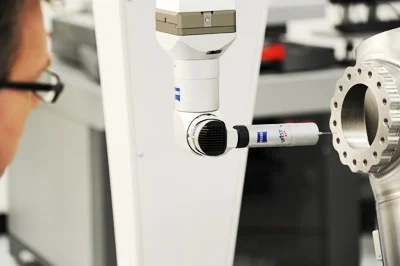
Coordinate measuring machines (CMMs) are mechanical systems that use a contact measuring probe and transducer technology to convert physical measurements of a surface into electrical signals that can be analyzed by specialized metrology software. CMMs range from basic XYZ read-outs utilizing hard-probes to fully-automated systems with articulating continuous contact probing that can perform CAD model-based inspections. The measurement envelope of CMMs ranges from desktop systems to those large enough to measure an entire car and beyond. Since volumetric accuracy is usually stated as an equation in which the error increases as a function of size, larger CMMs generally tend to have less accuracy then smaller systems. However, just because a CMM is large does not mean it cannot also be accurate. CMMs that are large and accurate exist but certainly cost much more. While both manual (free floating) and DCC (Direct Computer Control) CMMs can be programmed, DCC-CMMs are robotically driven by motors instead of the operator. This makes for huge time savings in inspecting many of a given part configuration, over and over again. However, with power, comes responsibility. Automated measurement systems such as DCC-CMMs have the possibility of a programming error which can lead to it being misused, causing damage to the CMM or the part being measured, however newer software reduces the chances of such accidents.
The sensors for CMMs are not limited to touch probes. Advanced systems can also include continuous contact scanning probes, indexable vision sensors, laser scanning heads, and even surface finish probes. CMMs measure points and DCC-CMMs can control the direction in which these points are measured. Everything else is in the software, which makes the features of the software integral to the machine’s output. It’s important that the software offer the right combination of power and ease of use. All CMM software provides for taking measurements of points and basic geometry such as planes, circles, and lines, as well as cylinders, spheres, cones, and more. Operations are then performed on the geometrical elements which are then generated into dimensional readings, compared against design tolerances, and distilled into reports. Newer CMM software allows for model-based inspection where the CMM measurements and program are written using a 3D CAD model of the part of interest. Special software modules exist for complex parts containing airfoils, gears, or free-form non-prismatic geometry. However, contact sensors generally do not work well for dimensional inspection applications where the object is soft, elastic, or extremely small.
What is a Structured Light 3D Scanner?

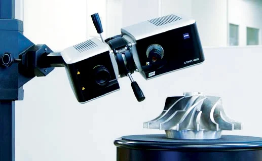
One of the most common types of non-contact 3D scanning is structured light scanning. Sometimes also called white light or blue light scanning, this method of 3D scanning includes a projection light source which could be either white or blue light, and involves projected light and typically 1 or 2 cameras to measure the three-dimensional surfaces of an object via triangulation. To obtain scan data via triangulation, a pattern of light is projected usually in a series of parallel lines which become distorted on the surface of the object when viewed from a perspective different from the projector. Each camera utilized captures this distortion from varying, sometimes multiple angles, and triangulates the distance of numerous points on the part being scanned. Finally, these three-dimensional coordinates are used to digitally reconstruct the details of the object. As part of the post-processing, the digital “mesh” of facets is created from these scans at multiple orientations via software which cleans the scans up, merges the multiple scans, and stitches them all together. This meshed representation can then be used to perform dimensional inspection operations or reverse engineering.
This method of 3D scanning can be used on objects and quickly captures a high volume of data without impacting the surface of the object. Because structured light scanners operate with immense speed relative to measuring devices like CMMs that measure at each area that the probe comes into contact with, producing a sparse amount of points, structured light scanning offers advantages, particularly with data density, that are simply not feasible on a CMM. Like CMMs, structured light scanners comes in various sizes and can be used on everything from the micro scale such as orthodontics all the way to large volume objects such as airplanes (when used in conjunction with retro-reflective targets and photogrammetry). Other applications for this technology would be when contact probes like CMMs are not appropriate. For example, if the object is elastic, delicate, or otherwise difficult to handle, structured light scanning can be used without any physical contact with the object being measured. The use of structured light scanning on a specific application depends on factors including surface characteristics such as reflectivity, transparency, and roughness. In some cases, structured light scanning is not an appropriate method because diffraction and reflection can affect the measurements. This can usually, but not always, be overcome either by special system settings or by the application of a fine and easily removable chalk spray.
Consider All Factors
There are several factors to consider when choosing measurement equipment. It is important to understand how each of these factors will affect your application’s measurements.
- Accuracy of measurement results
- Portability of the system
- Size of the parts being measured
- Features that will be measured
- Degree of automation required during measurement
- Speed of the measurement process
- Cost of the system
- Cost of training operators
CMMs still and will continue to play a vital role in today’s dimensional metrology applications, however structured light scanning can offer many advantages in scenarios where:
- the given application has a large amount of complex geometry
- a high percentage of the parts need to be measured
- the parts can’t accommodate contact measurement
- the measurement process needs to be very fast
For years, Industrial Inspection & Analysis has been one of the leading dimensional measurement laboratories in the United States. Servicing nearly every industry, our team provides industry-leading precision measurement, inspection, engineering, and quality assurance services. If your organization is in the process of offloading physical in-house work, consider working with us. We're proud to support organizations by providing high-quality dimensional measurement services, allowing organizations to meet their dimensional measurement requirements while optimizing their costs.


