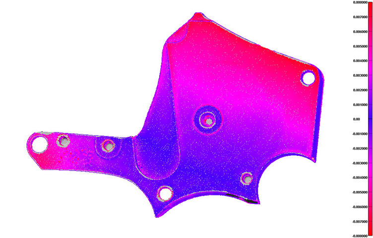
3D Scanning to Map Part Shrinkage

The right laser scanning equipment can accurately define localized shrinkage in a cast or molded component. This method is often used to troubleshoot tooling by developing surfaces of the sink area and using the new CAD geometry to modify the tooling insert. On small parts, the organic-shaped sink can be replicated to 2 or 3 ten-thousandths of an inch. Miniature sinks can be replicated to less than a micron using white light scanning or laser micro-scanning.
This is a very precise method of obtaining results when qualifying tooling. A typical turn-time to receive new CAD data is 24 to 48 hours, allowing inserts to be accurately modified quickly. The process has been successfully applied to sealing surfaces, bearing areas, and any application where shape is critical. This method is useful when part wall thickness cannot be changed or process modifications cannot adequately compensate for sinks.
Why Choose IIA?
Data capture with 3D laser scanning is efficient, flexible, and highly accurate — and it’s one of our specialties at Industrial Inspection & Analysis (IIA). Our labs are equipped with an extremely wide range of 3D scanners and CT machines, and our experts know which one will best meet your project needs. We have the equipment and expertise to scan objects ranging from the face of a penny to the contours of a fighter jet — and everything in between.
Benefits of Outsourcing
Many companies choose to outsource their 3D scanning needs to an established third-party provider like IIA. This allows manufacturers to focus on their core business, while we focus on creating accurate 3D models for them. In terms of efficiency and cost, this can be far more productive than purchasing a scanner for in-house use.
Learn more about IIA’s 3D Laser Scanning


